Atomic Theory
Everything is made of Atoms, that includes this universe, humans, materials, gas etc. An atom consists of a nucleus (proton + neutron) and electrons. Usually, these electrons surround the nucleus in the form of a cloud expressed as wave-particle duality not like a single orbit. In the copper atom, the electron in the outermost shell is free to move when a force is applied in the form of a moving magnetic field.
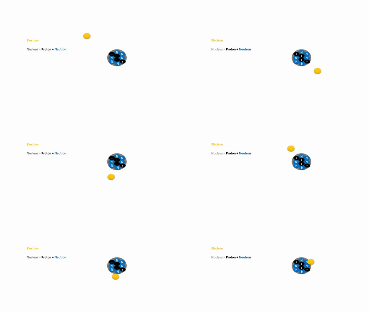
Electron and Proton
Electron is a negatively charged subatomic particle that can be either bound to an atom or free (not bound).
Proton is a subatomic particle found in the nucleus of every atom. The particle has a positive electrical charge, equal and opposite to that of the electron.


Drift Velocity of Electron
Drift velocity is the average velocity with which electrons 'drift' in the presence of an electric field. It's the drift velocity (or drift speed) that contributes to the electric current.

Magnetic Field or Flux
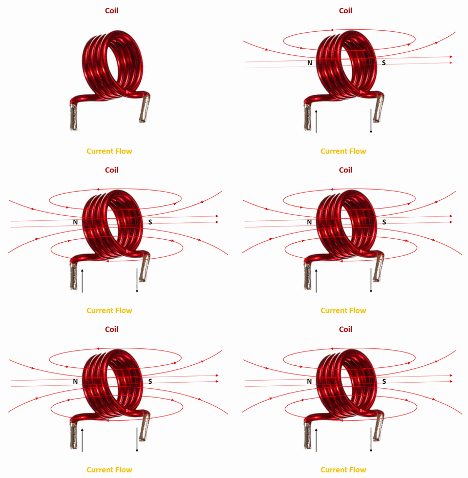
A region around a magnetic material or a moving electric charge within which the force of magnetism acts. Magnetic fields are produced by moving electric charges in the material, in a permanent magnet a static magnetic field is always present surrounding it. The magnetic field is also called as magnetic flux measured in Weber's/Gauss/Tesla always goes from north to south polarization of the magnet.

Electromagnetism
Creating electromagnetic fields by passing electric current through a conductor.
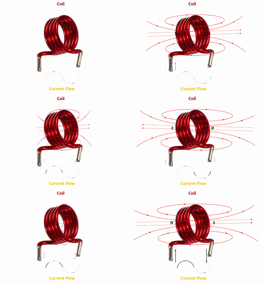
Dynamic Magnetic Field With AC current excitation
Static Magnetic Field With DC current excitation
Faradays Law of electromagnetic induction
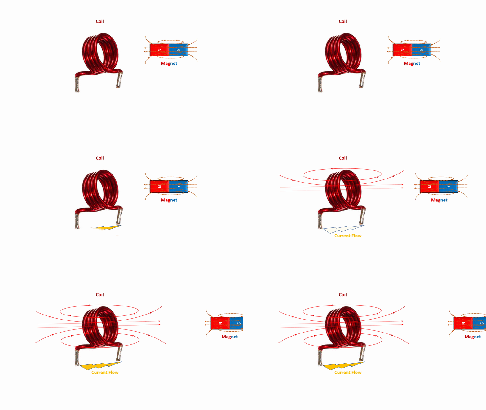
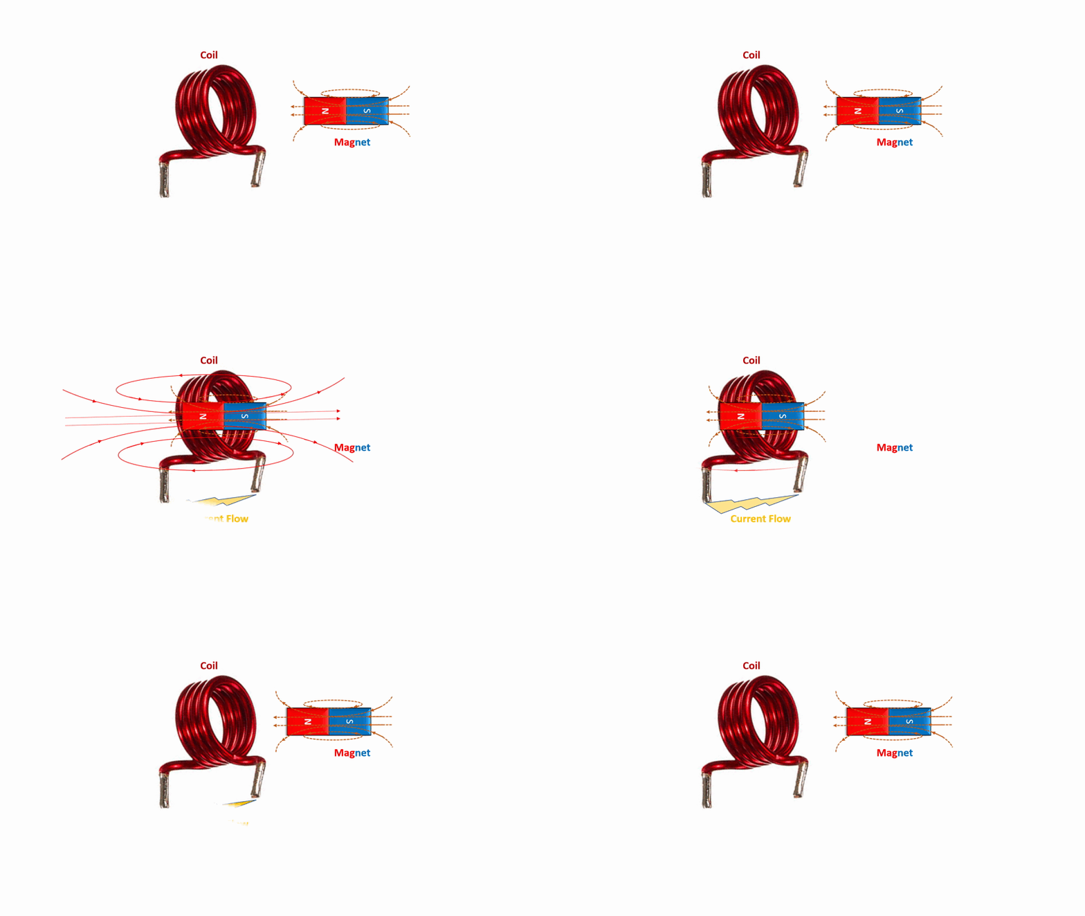
Electric Generator and Transformer Working Principle
"Whenever a dynamic/moving magnetic field cuts a conductor, an electromotive force (EMF) is induced in the conductor which will create a current if the circuit is closed:"
Electric Motor Working Principle
"Whenever a current carrying conductor is placed in a magnetic field, it experiences a torquing force."
Electric Charge
Electric charge is the physical property of matter that causes charged matter to experience a force when placed in an electromagnetic field. Electric charge can be positive or negative. Like charges repel each other and unlike charges attract each other.
The SI unit of electric charge is the coulomb (C).
Electric Field (E-Field)
Electric field is defined as the electric force per unit charge. The direction of the field is taken to be the direction of the force it would exert on a positive test charge. The electric field is radially outward from a positive charge and radially inward toward a negative point charge.
The SI unit is volts per metre (V/m).

Magnetic Field (B-Field)
The Magnetic field is defined as a vector field created due to moving charges i.e electrons.
The unit is Newtons per meter per ampere or Tesla or Gauss.

Electricity Generation – Faradays 1st Law
Electricity travels close to the speed of light in the form of electromagnetic fields generated by the resultant force of E-Field and B-Field due to electron drift. Faraday’s first law of electromagnetic induction states, “Whenever a conductor is placed in a varying magnetic field, an electromotive force is induced. Likewise, if the conductor circuit is closed, a current is induced, which is called induced current.”
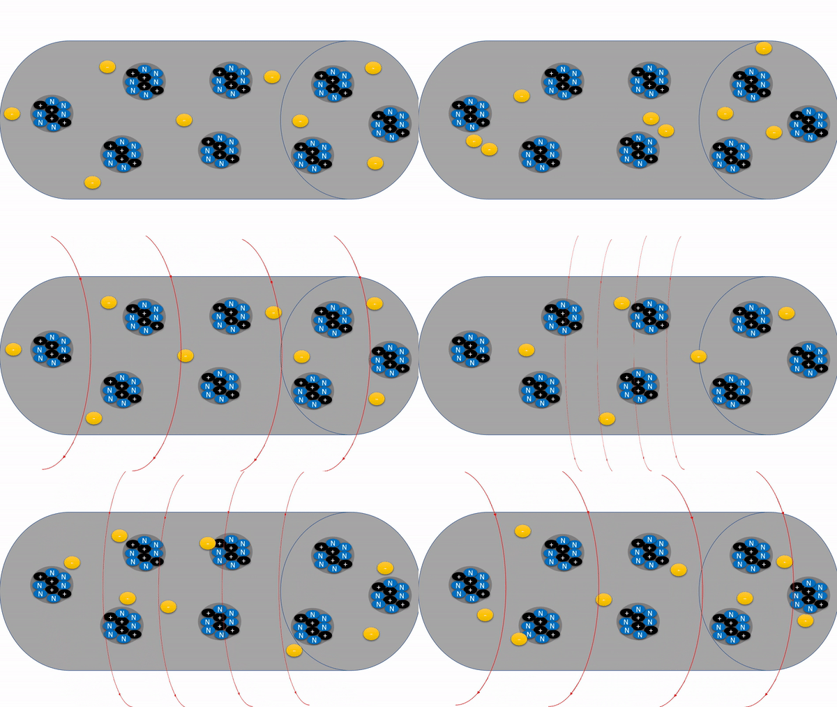

The above image shows when a magnetic field cuts a conductor the free electrons in the atom experience a force and makes it move from its shell. The charge around the electron generates an E-Field which pushes (repels) the other electron to move and so on...This will result in creating a magnetic B-Field. Hence the resultant force of E-Field and B-Field travels travels at the speed of light is called Electricity.
Current (I)
The flow of electric charges or electrons is called current. The SI unit is Amperes (A).
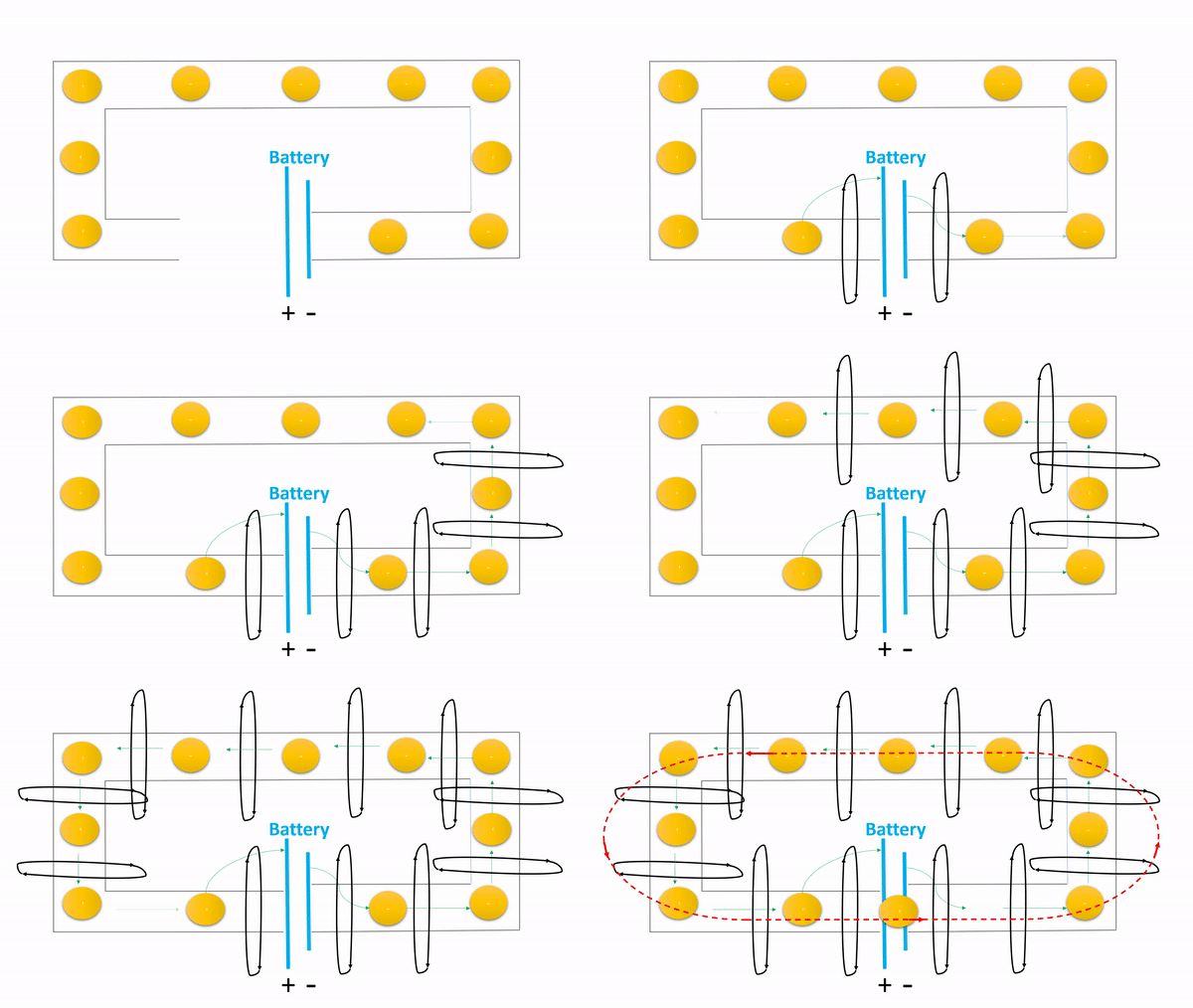
Question: Why it is said "Electricity travels at the speed of light" when the drift velocity of electrons is slow?
Answer: The resultant vector force of electrical E-Field and magnetic B-Field travels close to the speed of light.

Voltage (V)
The force or potential required to move the electrons is called voltage. The SI unit is Volts (V).
Alternating Current (AC)
Alternating current is an electric current which periodically reverses direction and changes its magnitude continuously with time in contrast to direct current which flows only in one direction.

Direct Current (DC)
The direct current meaning is when the electrical current flows consistently in a single direction.

Power (P)
In an electric circuit, instantaneous power is the time rate of flow of energy past a given point of the circuit.
Electric Load
In an electric circuit, electric load is nothing but the current consumption.
Power Factor (PF)
The phase angle between current and voltage is called the power factor, the power factor varies depending on the type of load. It is also defined as the ratio of apparent power to real/active power.
Resistive Load: The power factor is unity because current and voltage are in phase by θ = 0deg.
Cos θ = 1
Inductive Load: The power factor is lagging because current lags the voltage by θ >= 90deg.
Capacitive Load: The power factor is leading because current leads the voltage by θ <= 90deg.


DC Power (Pdc)
The product of DC voltage (V) and current (I) is called Power (P). The SI unit is Watts (W).
Pdc = V*I Watts
AC Power (Pac)
The product of AC voltage (V), current (I) and Power Factor (Cos θ) is called AC Power (Pac). The SI unit is Volt-Ampere (VA).
Pac = V*I Cos θ VA
Active Power (P)
Active power is the power that continuously flows from source to load in an electric circuit. It is also called as true power or real power or actual power or useful power. Active power is fully absorbed by load if it is resistive type. The SI unit is Watts (W).
P = V*I Watts
Reactive Power (Q)

Reactive power is the power that continuously flows from source to load and returns back to source if the load is inductive or capacitive.
Is is also called as ‘Imaginary power’ or ‘Watt less power’ or ‘Useless power’ or Complex power. The reactive power is the energy stored in the B-Field of inductor and energy stored in E-Field of capacitor. The SI unit is Watts (VA).
Q = V*I Sin θ VAR

Apparent Power (S)
The complex sum of real power and reactive power is called the apparent power and can be expressed like S = P+jQ

Ohms Law

Ohm's law states that the current through a conductor between two points is directly proportional to the voltage across the two points because the resistance is constant when the temperature is constant.
V = I*R
Short Circuit
In short circuit conditions, the resistance in the circuit becomes zero causing current to go infinite and makes the voltage to zero.
I = V/R = V/0 = Infinite Current
V = I* R = I * 0 = 0V
Open Circuit
In open circuit conditions, the resistance becomes in the circuit becomes infinite thus no current flow and voltage becomes infinite.
Impedance (Z)
It is defined as the complex sum of resistance and reactance. The SI unit of impedance is ohms.
Z = R ± J X
Inductive Reactance (XL)
In electrical circuits, inductive reactance is the opposition presented to alternating current by inductance.
Reactance is a fictitious (imaginary) term.
Inductive Reactance (XL) = 2* π * Frequency(F) * Inductance(L) Ohms(Ω)
Capacitive Reactance (XC)
In electrical circuits, capacitive reactance is the opposition presented to alternating current by inductance.
Reactance is a fictitious (imaginary) term.
Capacitive Reactance (XC) = 1/ (2* π * Frequency(F) * Capacitance (C)) Ohms(Ω)
Resistor (R)
A resistor is a passive two-terminal electrical component that exhibit electrical resistance to limit the flow of electrons. The SI unit of resistor is ohms.
R = V/I


Equations and Formulas
Inductor (L)
An inductor is a passive electronic component which is capable of storing electrical energy in the form of magnetic field and opposes to sudden change in current by inducing a voltage.

Operation
Inductor offers a high impedance to AC (block AC) and low impedance to DC (pass DC).
Inductor opposes sudden change in current flowing through it by increasing its voltage VL, thus it is affected by B-Field.

Equations and Formulas

Capacitor (C)
A capacitor is a device that stores electrical energy in an electric field. It is a passive electronic component with two terminals.

Operation
Capacitor offers a high impedance to DC (block DC) and low impedance to AC (pass AC).
Capacitor opposes sudden change in its applied voltage by drawing/passing more current thru it, thus it is affected by E-Field.

Equations and Formulas


Example: Voltage and current calculation of capacitor


RC Resonant Frequency
The equation for the characteristic frequency (Fr) of the RC circuit is Fr = 1 / (2πRC).
So at the characteristic/resonant frequency (Fr), the capacitive reactance Xc will become equal to the value of resistance R.
LC Resonant Frequency
The equation for the characteristic/resonant frequency (Fr) of the LC circuit is Fr = 1 / [sqrt (2πLC)]
So at the characteristic/resonant frequency (Fr), the capacitive reactance Xc will become equal to the capacitive reactance XL

Kirchhoff's Voltage Law
Kirchhoff's voltage law states that the algebraic sum of the potential differences in any loop must be equal to zero as: ΣV = 0

Kirchhoff's Current Law
Kirchhoff's current law states that the algebraic sum of the currents entering a junction is equal to the sum of the currents leaving a junction.

Nodal Analysis For Voltage Divider Circuit
The mathematical method for calculating the voltage distribution between the circuit nodes. This method is also known as the node-voltage method since the node voltages are with respect to the ground.

Inductor Series and Parallel Circuit Analysis
The equations for inductors connected in series and parallel combinations shown below.

Capacitors Series and Parallel Circuit Analysis
The equations for capacitors connected in series and parallel combinations shown below.

Resistor Series and Parallel Circuit Analysis
The equations for resistors connected in series and parallel combinations shown below.

RC Series: Low Pass Filter (aka) Integrator
A simple RC circuit can be analyzed as a voltage divider circuit like shown, this will help to calculate practical output values.
Time constant T = RC
Input Signal = AC signal with DC offset

The above RC series circuit shall be analyzed in two the scenarios i.e while the capacitor is charging at t=0 and after capacitor is fully charged at t=∞.
Time t = 0 (Charging Period)

Time t = ∞ (After full charge period)

RL Series – High Pass Filter (aka) Differentiator
A simple RL circuit can be analyzed as a voltage divider circuit like shown, this will help to calculate practical output values.
Time constant T = L / R
Input Signal = AC signal with DC offset

The above RL series circuit shall be analyzed in two the scenarios i.e while the capacitor is charging at t=0 and after capacitor is fully charged at t=∞.
Time t = 0 (Energizing Period)

Time t = ∞ (After energized Period)

RLC Series Circuit
Here Vo = 0V


RLC Parallel Circuit


